An edge-lit lighting product can appear simple from the outside: a thin illuminated panel, a printed graphic or a glowing architectural surface. Inside, however, the optical system depends on a precise relationship between the LED source, the acrylic substrate, the extraction pattern, the reflector, the diffuser, the frame and the thermal environment. A light guide plate that is treated as an ordinary clear sheet may produce bright edges, dark centers, visible LED hotspots or inconsistent brightness from one production batch to the next.
For B2B buyers, the most useful question is not “What is the brightest LGP?” It is “Which design produces the required brightness uniformity, appearance, thickness and power level in my finished assembly?” A panel for a 300 mm retail sign, a 1,200 mm ceiling light, a menu board and an illuminated shelf each require different pattern density, LED arrangement and optical stack.
This guide explains the engineering logic behind acrylic light guide panels. It covers how total internal reflection and micro-pattern extraction work, how laser dotting compares with printing and V-grooving, why LED pitch and edge coupling matter, how to define uniformity, which defects to inspect and what information to send a supplier before prototyping. It is written for signage manufacturers, lighting companies, display integrators, fixture designers and importers who need repeatable LGP performance rather than a generic clear panel.
What Is an Acrylic Light Guide Panel?
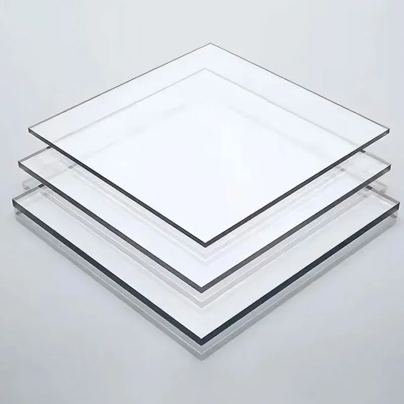
An acrylic light guide panel is an optical PMMA plate engineered to receive light from one or more edges, transport it by internal reflection and extract it across a broad surface through a controlled micro-pattern.
A clear acrylic sheet transmits light, but an LGP must also manage where light leaves the sheet. Without an extraction pattern, much of the injected light remains trapped by total internal reflection or escapes unevenly. The dot or groove pattern intentionally disrupts the guided light so that it exits toward the viewing surface.
PMMA is widely used because clear grades can transmit up to approximately 92% of visible light and have a refractive index near 1.49. These properties allow efficient light transport when the sheet, edges and pattern are properly designed. PMMA is also lightweight, machinable and available in thicknesses suitable for thin illuminated assemblies.
AML supplies optical acrylic solutions for edge-lit applications. Buyers evaluating an lgp panel should identify the panel dimensions, LED arrangement, target brightness, viewing distance and optical stack before requesting a price, because the extraction pattern is part of the component design rather than a universal texture.
How an Acrylic Light Guide Panel Works
An acrylic light guide panel works by coupling LED light into a polished edge, guiding it through PMMA by total internal reflection and releasing controlled portions of the light at patterned extraction points.
When light enters the acrylic at a suitable angle, it reflects repeatedly between the front and rear surfaces instead of immediately escaping. This is total internal reflection. The extraction pattern changes the local angle or scattering behavior. At each dot, groove or printed feature, a portion of the guided light is redirected out of the panel.
The pattern is normally sparse near the LED edge because light intensity is highest there. It becomes denser or more aggressive farther from the source, where less light remains. The objective is not to extract the same percentage at every point; it is to produce a visually even surface after accounting for the decreasing amount of light traveling through the plate.
A practical LGP system usually includes several optical elements:
LED source: Provides light at one, two or four edges.
Light guide plate: Transports and extracts the light.
Reflector: Returns backward-emitted light toward the viewing side.
Diffuser: Blends local brightness variation and hides the dot pattern.
Graphic or optical film: Creates the final visual surface.
Frame and thermal path: Align components and remove LED heat.
Changing any one layer can change the result. A denser diffuser may hide hotspots but reduce total brightness. A highly reflective rear film may improve output but reveal frame gaps. A new LED package may have a different emission angle and require a modified input edge or dot pattern. The LGP should therefore be developed as part of the assembly.
Why Acrylic Light Guide Panel Uniformity Is a System Property
Definition: Uniformity is the consistency of luminance or illuminance across the active emitting area under defined measurement conditions.
Uniformity is often described with a ratio such as minimum luminance divided by average luminance, or minimum divided by maximum. These formulas produce different values, so a specification must state which one is being used. A supplier and buyer can both report “90% uniformity” while referring to different calculations.
Two common formulas are:
Minimum-to-average uniformity = minimum measured value ÷ average measured value × 100%
Minimum-to-maximum uniformity = minimum measured value ÷ maximum measured value × 100%
For example, if nine measurement points range from 820 to 1,000 cd/m² and the average is 930 cd/m², the minimum-to-average uniformity is about 88.2%, while minimum-to-maximum uniformity is 82%. Both are mathematically correct, but they communicate different performance.
The measurement grid also matters. A five-point test may miss edge bands and local hotspots. A nine-point or denser grid gives more information, while imaging photometry can reveal continuous patterns. The distance from the edge, warm-up time, ambient light, LED current, diffuser and graphic must be fixed during testing.
Commercial projects may set different acceptance thresholds depending on use. A decorative wall may tolerate more variation than a medical viewer or premium retail display. Instead of assuming one universal percentage, define the calculation, points, active area, optical stack and visual defect criteria.
Acrylic Light Guide Panel Pattern Technologies Compared
Pattern technology is the manufacturing method used to create optical extraction features on or within the light guide plate.
Laser dotting, screen printing, inkjet printing and mechanical V-grooving are common approaches. Each can produce a functional LGP when the pattern is designed correctly, but they differ in tooling, flexibility, repeatability and appearance.
| Pattern Method | How It Extracts Light | Strengths | Limitations | Best-Fit Projects |
|---|
| Laser dotting | Creates microscopic surface features with controlled density | Digital flexibility, no printing ink, suitable for custom sizes and revisions | Cycle time and result depend on laser control and substrate response | Custom light boxes, prototypes, varied formats |
| Screen printing | Prints reflective or scattering dots onto the plate | Established process and efficient for repeated volume | Requires screens, ink control and curing; design changes need new tooling | Stable high-volume formats |
| Inkjet printing | Deposits a digitally controlled optical ink pattern | Variable data, digital pattern adjustment and reduced physical tooling | Ink formulation, adhesion and curing must be controlled | Short-to-medium runs and adaptive patterns |
| V-groove engraving | Uses machined lines or grooves to redirect guided light | Strong directional extraction and visible decorative effects | Tool marks, directional artifacts and machining time | Decorative panels, signage and line-light effects |
Laser dotting is attractive for custom B2B projects because the pattern can be changed digitally without manufacturing a new screen. The dot size, spacing and distribution can be adjusted for panel size, LED position and target uniformity. However, “laser-dotted” does not automatically mean uniform. The optical model, machine calibration, edge condition and diffuser still determine performance.
Printed patterns can be cost-effective for repeat production. Their optical behavior depends on dot geometry, ink reflectivity, thickness and adhesion. Process variation can change brightness if ink viscosity, screen condition or curing changes. Buyers should ask how the printing process is controlled and how first-article panels are compared with the approved master.
V-grooves can create efficient directional extraction, but a line pattern may be more visible than a fine dot pattern. This can be desirable for decorative lighting and less suitable where the emitting face must appear completely smooth at close viewing distance.
How to Define the Design Inputs Before Pattern Development
Design inputs are the mechanical, optical, electrical and visual requirements used to calculate or iterate an LGP extraction pattern.
The supplier cannot optimize a plate from width and height alone. At minimum, the design package should include:
Finished active area and total panel dimensions
Plate thickness and allowed assembly depth
One-edge, two-edge or four-edge LED configuration
LED model, package size, pitch, viewing angle and color temperature
Driver current and dimming method
Reflector and diffuser materials
Graphic, print or front cover transmission
Target luminance, illuminance or visual brightness
Uniformity formula and acceptance threshold
Viewing distance and permitted edge border
Operating temperature and heat-sink arrangement
Prototype quantity and mass-production volume
When these inputs are incomplete, the supplier may use a standard pattern that performs reasonably in a generic test box but not in the customer’s assembly. For example, changing from a one-edge to a two-edge LED layout changes the intensity field and pattern symmetry. Replacing a thin diffuser with a dense opal sheet changes both brightness and visual blending.
If the project is early in development, provide a range rather than omitting the information. A supplier can model or prototype two configurations, such as 4 mm and 6 mm plate thickness, or one-edge versus two-edge lighting. The decision can then be based on measured performance and total system cost.
Acrylic Light Guide Panel Thickness and Panel Size
Definition: LGP thickness affects edge coupling, stiffness, optical path, assembly depth, weight and the pattern required to maintain uniform brightness.
Thin plates support slim products, but they offer a smaller input edge for coupling LED light and may be more sensitive to flatness, frame pressure and edge alignment. Thicker plates can accept more light at the edge and provide greater stiffness, but they add weight, material cost and assembly depth.
Panel size changes the distance that light must travel. A small plate can often be lit from one edge, while a larger panel may need two or four illuminated edges to reduce center darkness and maintain efficiency. The relationship is not linear because LED optics, pattern density, reflector quality and diffuser loss also influence the result.
The substrate should be optical grade. General-purpose acrylic board may look clear to the eye but can have different optical purity, thickness tolerance, surface condition or internal stress. LGP projects should use material whose transmission, flatness and processing route are appropriate for optical work.
Mechanical design must also prevent bowing. A warped plate changes the air gaps and contact conditions between the reflector, diffuser and frame. Local contact may create bright marks or Newton-ring-like effects, while excessive gap can reduce optical blending. The frame should support the panel without introducing stress.
LED Selection and Edge Coupling
Edge coupling is the controlled transfer of LED output into the LGP input edge with minimal loss and minimal visible source pattern.
The LED package should align with the plate edge. If the emitting center is above or below the acrylic, a large portion of light may miss the guide or enter at inefficient angles. The mechanical tolerance of the LED board, frame and plate therefore affects optical performance.
LED pitch influences hotspot visibility. Closely spaced LEDs create a smoother input field but increase component count, heat and cost. Wider spacing reduces component count but can create bright cones near the edge. The extraction pattern and any input-edge optical feature must be designed around the selected pitch.
The input edge should be clean and appropriately polished. Saw marks scatter light before it enters the plate and may create a bright edge band. Over-polishing or contamination can also change coupling. Edge tape, reflective film or optical coupling materials may be used, but their compatibility and aging must be validated.
Color temperature and binning affect appearance. Adjacent modules using different LED bins can look mismatched even when the LGP is identical. For long signage or multi-panel installations, specify LED bin control and compare modules together.
Thermal design is essential. LED output and lifetime depend on junction temperature. U.S. Department of Energy material explains that white LED packages may be rated around 50,000 hours to a defined lumen-maintenance level, but the actual system life depends on current, heat and other components. A nominal 50,000-hour rating equals about 5.7 years of continuous 24-hour operation, yet poor heat removal can reduce both brightness and useful life.
Reflector, Diffuser and Optical Film Selection
Definition: The optical stack controls how extracted light is recycled, blended and presented to the viewer.
A rear reflector sends backward-emitted light toward the front. High reflectance improves utilization, but wrinkles, gaps and contamination can create visible defects. The reflector should lie flat without trapping dust or creating local contact marks.
The diffuser blends dot-level variation and LED hotspots. A higher diffusion level generally improves visual smoothness but reduces transmitted brightness. The correct diffuser is therefore a compromise between uniformity and efficiency. It should be tested with the actual graphic and viewing distance.
Brightness-enhancement films, prism films and reflective edge tapes can improve system performance, but they add orientation and assembly requirements. A prism film installed in the wrong direction may not deliver the intended gain. Film edges can also become visible in thin frames.
Printed graphics may absorb substantial light. A white ink layer, colored image and protective laminate can change both total output and local uniformity. The LGP should be evaluated behind the production print, not only behind a clear diffuser.
When the front layer is made from clear acrylic sheets, account for surface reflections, thickness, edge treatment and any printed masking border. A clear cover can protect the diffuser and graphic, but it may add glare if the environment has strong overhead lighting.
Designing the Dot Density Gradient
A dot density gradient varies extraction strength across the plate so that regions with less remaining guided light extract a larger proportion of it.
Near the LED edge, the plate contains abundant light. If the dot pattern is too dense there, the edge becomes excessively bright and little light reaches the center. Farther from the source, the pattern must extract more aggressively because the guided light has been depleted by previous dots and material loss.
The gradient can be changed by dot size, spacing, shape, depth or optical ink coverage. A design may hold dot size constant and change spacing, or combine both variables. The optimal pattern depends on LED directionality, plate thickness, panel aspect ratio and whether one or multiple edges are lit.
Research on light guide plates shows that optimized micro-pattern design can significantly improve illuminance uniformity. In practice, simulation provides a starting point, while prototype measurement is used to tune the pattern. Material variation, machine response and assembly gaps are difficult to model perfectly.
For rectangular panels, corner behavior requires attention. Corners far from an illuminated edge may be dark, while corners near two lit edges may be bright. Pattern symmetry should match the LED layout rather than the outer panel shape alone.
Masking borders can hide the most difficult edge zone, but the active area and bezel width must be agreed early. A pattern designed with a 20 mm concealed border may look poor if the customer later reduces the border to 5 mm.
Prototype Measurement and Optical Validation
Definition: Optical validation compares a production-intent prototype against quantitative brightness, uniformity, color and visual-defect criteria.
The prototype should use the intended LED board, driver, reflector, diffuser, frame and printed graphic. A bare LGP test is useful for development but does not predict the final customer-facing appearance.
Before measurement, allow the LED system to reach a stable operating temperature. Record ambient temperature, input power, current and warm-up time. Measurements should be taken at defined points within the active area, excluding any agreed masked border.
A basic nine-point grid includes corners, edge centers and the panel center. Larger or high-specification panels may require a denser grid or imaging photometer. Record minimum, maximum and average values and calculate the agreed uniformity formula.
Visual inspection should evaluate:
LED hotspots and bright input-edge bands
Dark center or dark corner zones
Visible dot, line or moiré pattern
Scratches, contamination and inclusions
Frame shadows and reflector gaps
Color-temperature variation
Brightness differences between modules
The prototype should also be tested at the intended viewing distance. A dot pattern visible at 100 mm may disappear at 2 m, while a broad brightness gradient may remain objectionable from across a room. Acceptance should reflect real use.
Common Acrylic Light Guide Panel Defects and Root Causes
Definition: LGP troubleshooting links each visible defect to likely causes in the LED source, edge coupling, pattern, optical films, material or assembly.
| Observed Defect | Likely Causes | Corrective Direction |
|---|
| Bright band at LED edge | Pattern too dense near input, poor blending, LEDs too close to active area | Reduce near-edge extraction, add mixing distance or revise diffuser |
| Dark center | Insufficient far-field extraction, one-edge layout too demanding, excessive optical loss | Increase distant pattern density, add lit edge or improve reflector |
| Visible LED hotspots | Wide LED pitch, poor edge alignment, inadequate diffuser | Adjust pitch, coupling geometry, input optics or diffuser |
| Patchy bright and dark spots | Pattern variation, dust, reflector wrinkles, local contact | Inspect pattern process, clean assembly and flatten layers |
| Low overall brightness | Poor edge polish, weak coupling, dense diffuser, low-reflectance backing | Measure losses layer by layer and improve coupling or films |
| Module-to-module color difference | LED bin variation, driver current difference, graphic variation | Control LED bins, electronics and printed layers |
| Scratches visible when lit | Handling damage or contamination | Improve protective film, work surface, cleaning and packaging |
| Panel warping | Heat, frame stress, insufficient support or material flatness | Improve thermal path, clearance, support and incoming inspection |
Troubleshooting should change one variable at a time. If the LED current, diffuser and dot pattern are changed simultaneously, the team cannot identify which adjustment improved or worsened the result. A controlled design-of-experiments approach is faster than repeated unrecorded trial and error.
Mechanical Design, Thermal Movement and Assembly Tolerance
Mechanical integration keeps the LGP aligned, flat and free to expand without creating optical artifacts or stress damage.
PMMA expands more than metal. A large plate installed in a rigid aluminum frame needs clearance for temperature change. Tight clamping can cause bowing, edge stress or cracking, while excessive looseness may create rattling or inconsistent optical gaps.
The LED-to-edge distance must remain controlled. If the plate moves away from the LED board, coupling efficiency falls. A flexible gasket or locating feature can hold alignment while allowing in-plane expansion. The design should avoid hard particles that can scratch the optical edge.
Frame pressure should be distributed. Point loads can create local contact between the LGP, diffuser and reflector, producing bright spots. Fasteners and clips should sit outside the active area where possible.
Heat from the LED board must be conducted to a suitable heat sink. The LGP should not be used as the primary thermal path. Elevated temperature can change LED output, accelerate adhesive aging and distort thin plastic layers.
Assembly tolerances should be included in the optical prototype. A hand-built sample with perfect alignment may outperform production units if the design has no tolerance margin. Pilot production should include parts at realistic dimensional extremes.
Surface Quality and Cleanroom-Like Handling
Optical handling protects the LGP from scratches, dust, fingerprints and inclusions that become highly visible when the panel is illuminated.
A small scratch that is difficult to see in ambient light can glow brightly after LED light enters the plate. Dust particles between the plate and reflector may appear as dark or bright points. Fingerprints can change local extraction and become difficult to remove after assembly.
Protective film should remain on both faces until the relevant assembly step. Cutting and dotting areas should be clean, with controlled removal of chips and debris. Operators should use clean gloves and avoid touching polished input edges.
After patterning, the panel should be inspected under edge illumination because this reveals defects more effectively than overhead light. The acceptance standard should distinguish between defects inside the active area, masked border and non-visible edge.
Packaging should keep the patterned surface from rubbing against another sheet. Interleaving, corner protection, rigid cartons or crates and moisture protection may be required for export. Labels should identify panel orientation, LED edge and batch.
How to Qualify a Light Guide Plate Manufacturer
Manufacturer qualification verifies optical design capability, substrate control, pattern repeatability, inspection and support for prototype-to-volume transfer.
A supplier should be able to discuss the full assembly rather than quote only a sheet size. Ask how the pattern is developed, which inputs are required, how prototypes are measured and how the approved pattern is locked for production.
AML positions itself as a light guide plate supplier and manufacturer with acrylic production capabilities and custom design support. Its broader manufacturing footprint includes production bases in China and Indonesia and multiple acrylic production lines. For LGP projects, buyers should connect this scale with project-specific optical controls.
Useful qualification questions include:
Which PMMA grade and production method are used?
How are thickness, flatness and optical quality inspected?
Which pattern methods are available?
Is optical simulation used, and how is it validated?
Which measurement grid and uniformity formula are standard?
Can the supplier test with the customer’s LED and optical films?
How is the approved digital pattern revision controlled?
What defects are inspected under edge illumination?
How are panels cleaned, protected and packed?
What records support repeat production?
A strong supplier should also state the limits of the initial quotation. When the final LED board and diffuser are not yet selected, the price may cover a standard LGP or a prototype phase rather than guaranteed final-system brightness.
Prototype-to-Mass-Production Workflow
The prototype-to-production workflow freezes optical inputs, validates performance and controls design revisions before volume manufacturing.
Requirement definition: Confirm active area, thickness, LED layout, optical stack and acceptance metrics.
Initial optical design: Develop a simulated or experience-based dot distribution.
Prototype manufacturing: Produce a small set using production-intent substrate and patterning.
Assembly test: Build prototypes with actual LEDs, reflector, diffuser and graphic.
Measurement: Record brightness, uniformity, power, temperature and visual defects.
Pattern revision: Adjust the gradient or system components based on controlled results.
Golden sample: Approve and retain a complete illuminated assembly or panel reference.
Pilot run: Confirm repeatability across multiple production panels.
Design freeze: Lock panel drawing, pattern file, material, LED and optical films.
Mass-production inspection: Use agreed sampling, optical tests and traceability.
Revision control is especially important. A small change to LED pitch, plate thickness or diffuser can make the approved dot pattern unsuitable. The purchase order should reference the correct drawing and pattern revision, and unapproved substitutions should trigger revalidation.
Acrylic Light Guide Panel RFQ Checklist
An LGP RFQ checklist gives the supplier enough technical information to quote the correct prototype, tooling, pattern development and production scope.
| RFQ Field | Required Information | Purpose |
|---|
| Application | Light box, display, ceiling light, shelf, sign or other use | Defines visual and operating priorities |
| Dimensions | Total size, active area, thickness and edge tolerances | Sets optical path and mechanical scope |
| LED system | Part number, pitch, edge count, PCB drawing, current and CCT | Controls input distribution |
| Optical stack | Reflector, diffuser, film, graphic and front cover | Determines brightness loss and blending |
| Performance | Target luminance/illuminance, uniformity formula and minimum value | Creates measurable acceptance |
| Viewing condition | Distance, ambient light and visible border | Sets practical defect criteria |
| Environment | Temperature, duty cycle, indoor/outdoor and humidity | Supports thermal and material design |
| Testing | Grid, warm-up time, instrument and sampling plan | Aligns supplier and buyer measurements |
| Quantity | Prototype, pilot and annual production volume | Guides pattern method and commercial terms |
| Delivery | Destination, packing, labels and schedule | Completes the export quotation |
Attach the LED board drawing, optical film datasheets and assembly cross-section where available. A short video of the current defect can also help the supplier understand hotspot, edge-band or uniformity problems.
Frequently Asked Questions About Acrylic Light Guide Panels
Definition: These FAQs address common technical and sourcing questions about PMMA LGP design and production.
1. Is an acrylic light guide panel the same as a clear acrylic sheet?
No. Clear acrylic is the substrate, while an LGP includes an engineered extraction pattern and controlled input edges. A plain clear sheet will not normally produce uniform surface illumination in an edge-lit assembly.
2. Which LGP pattern method is best?
There is no universal best method. Laser dotting is flexible for custom and changing formats, printing can be efficient for stable volume, and grooves can create directional effects. The best choice depends on size, volume, appearance and revision frequency.
3. How is LGP uniformity calculated?
Common calculations include minimum divided by average and minimum divided by maximum. The specification must state the formula, measurement grid, active area, warm-up time and optical stack.
4. Why is the center of an edge-lit panel dark?
Possible causes include insufficient far-field dot density, excessive optical loss, a panel that is too large for the LED layout, poor reflector performance or inadequate light entering the plate. Measure the complete assembly before revising the pattern.
5. Can one dot pattern be used with different LED boards?
Only after validation. Changes in LED pitch, package, viewing angle, current or distance from the edge alter the input field and may require a new pattern.
6. What should be approved before mass production?
Approve the complete illuminated system or a production-intent golden sample, including the plate, LEDs, reflector, diffuser, graphic, frame and driver. Lock the drawing and pattern revision after pilot-run verification.
Conclusion
A successful acrylic light guide panel is a matched optical system in which substrate, edge coupling, extraction pattern, LEDs, films, frame and testing method are developed together.
Uniform illumination does not come from acrylic clarity alone. It comes from controlling how light enters the plate, how it travels, where it is extracted and how the optical stack blends the result. The plate pattern must match the panel size, LED layout and active area, while the mechanical design must preserve alignment and remove heat.
For B2B projects, the fastest route to a reliable design is a measured prototype process. Define the performance formula, build with production-intent components, inspect the panel under illumination, revise one variable at a time and freeze the complete system before mass production.
AML Acrylic can review panel drawings, LED specifications, optical films, target uniformity and prototype quantities for light boxes, signage, display and lighting systems. A complete RFQ allows AML to recommend a suitable PMMA substrate and pattern-development route, reducing repeated sampling and helping the final assembly achieve more consistent brightness.
External References:
 EN
EN